
Page 422 - Gear Technology Solutions
P. 422
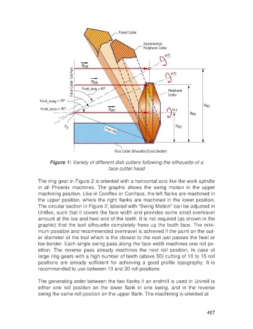
Figure 1: Variety of different disk cutters following the silhouette of a
                                                     face cutter head

                   The ring gear in Figure 2 is oriented with a horizontal axis like the work spindle
                   in  all  Phoenix  machines.  The  graphic  shows  the  swing  motion  in  the  upper
                   machining position. Like in Coniflex or Coniface, the left flanks are machined in
                   the upper position, where the right flanks are machined in the lower position.
                   The circular section in Figure 2, labeled with “Swing Motion” can be adjusted in
                   Uniflex, such that it covers the face width and provides some small overtravel
                   amount at the toe and heel end of the teeth. It is not required (as shown in the
                   graphic) that the tool silhouette completely frees up the tooth face. The mini-
                   mum possible and recommended overtravel is achieved if the point on the out-
                   er diameter of the tool which is the closest to the root just passes the heel or
                   toe border. Each single swing pass along the face width machines one roll po-
                   sition.  The  reverse  pass  already  machines  the  next  roll  position.  In  case  of
                   large ring gears with a high number of teeth (above 50) cutting of 10 to 15 roll
                   positions  are  already  sufficient  for  achieving  a  good  profile  topography.  It  is
                   recommended to use between 10 and 30 roll positions.

                   The generating order between the two flanks if an endmill is used in Unimill is
                   either  one  roll  position  on  the  lower  flank  in  one  swing,  and  in  the  reverse
                   swing the same roll position on the upper flank. The machining is oriented at


                                                                                                     407