
Page 404 - Gear Technology Solutions
P. 404
The results are the specific slot width or tooth thickness variations which would
be caused in each individual job if the master cutter would be used in connec-
tion with the original basic settings of each job. The next task is changing the
basic setting of each job, except the master job in order to eliminate the tooth
thickness variation. This is accomplished by axial cutter head vector shifts
(principle shown in Figure 5). The symmetry vector between the outside and
inside blades of each individual member is compared to the blade symmetry
vector of the same member of the master job. The discrepancy of the sym-
metry vector directions is used to calculate a basic setting change of each in-
dividual member of each job in order to minimize contact position changes be-
tween the original job and the consolidated version of the same job. The con-
solidation procedure uses a different master for the pinion and gear cutter con-
solidation. Different masters have a significant positive impact to the quality of
the consolidation results.
The second step of the Gleason consolidation method creates a non-existing
virtual master job. The virtual master job utilizes the same cutter head type as
the jobs of the consolidation variety but uses cutter head and blade geometry
parameters which are the result of an analysis of all jobs considered for the
consolidation. Such a virtual cutter may be different than each of the consoli-
dation jobs with all of its parameters except the number of blade groups. Due
to the fact that the virtual master is not bound to the cutter and blade parame-
ters of one particular consolidation job, it is possible to design the virtual cutter
with its virtual blades such that the range of variation between each parameter
of the virtual cutter and each cutter of the consolidation jobs is minimized.
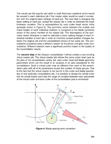
Figure 4: Blade spacing error correction
389