
Page 399 - Gear Technology Solutions
P. 399
with certain small differences. Those differences are, for example, the ratio be-
tween the two mating gear members which is realized with different combina-
tions of the pinion tooth number and the gear tooth number. Another potential
parameter which can differ between the members of the part family is the hy-
poid offset which in turn causes the pinion spiral angles to be different for each
different offset, even though the spiral angle of the ring gears is identical. In
some cases, certain optimizations to the contact geometry have been applied
in order to adjust particular members of the part family to different duty cycles
or application requirements.
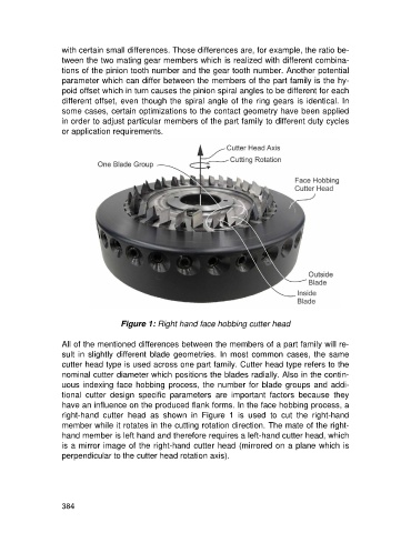
Figure 1: Right hand face hobbing cutter head
All of the mentioned differences between the members of a part family will re-
sult in slightly different blade geometries. In most common cases, the same
cutter head type is used across one part family. Cutter head type refers to the
nominal cutter diameter which positions the blades radially. Also in the contin-
uous indexing face hobbing process, the number for blade groups and addi-
tional cutter design specific parameters are important factors because they
have an influence on the produced flank forms. In the face hobbing process, a
right-hand cutter head as shown in Figure 1 is used to cut the right-hand
member while it rotates in the cutting rotation direction. The mate of the right-
hand member is left hand and therefore requires a left-hand cutter head, which
is a mirror image of the right-hand cutter head (mirrored on a plane which is
perpendicular to the cutter head rotation axis).
384