
Page 364 - Gear Technology Solutions
P. 364
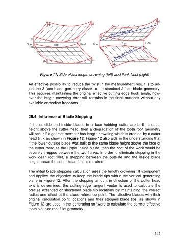
Figure 11: Side effect length crowning (left) and flank twist (right)

                   An effective possibility to reduce the twist in the measurement result is to ad-
                   just the 3-face blade geometry closer to the standard 2-face blade geometry.
                   This requires maintaining the original effective cutting edge hook angle, how-
                   ever the length crowning error still remains in the flank surfaces without any
                   available correction freedoms.


                   26.4  Influence of Blade Stepping

                   If  the  outside  and  inside  blades  in  a  face  hobbing  cutter  are  built  to  equal
                   height above the cutter head, then a degradation of the tooth root geometry
                   will occur if a gearset member has length crowning which is created by a cutter
                   head tilt k as shown in Figure 12. Figure 12 also aids in the understanding that
                   if the lower outside blade was built to the same blade height above the face of
                   the cutter head as the upper inside blade, then the root of the work would be
                   severely stepped between the two flanks. In order to eliminate stepping in the
                   work  gear  root  fillet,  a  stepping  between  the  outside  and  the  inside  blade
                   height above the cutter head face is required.

                   The initial blade stepping calculation uses the length crowning tilt component
                   and applies the objective to keep the blade tips within the vertical generating
                   plane in Figure 12. After the stepping amount in direction of the cutter head
                   axis  is  determined,  the  cutting-edge  tangent  vector  is  used  to  calculate  the
                   precise extended or shortened blade tip locations by maintaining  the correct
                   radius and offset at the blade reference point. The effective blades with their
                   original  calculation point  locations and their stepped  blade  tips, as shown in
                   Figure 12 are used in the generating software to calculate the correct effective
                   tooth slot and root fillet geometry.


                                                                                                     349