
Page 359 - Gear Technology Solutions
P. 359
In order to obtain the effective angles, the relationship between the cutting ve-
locity vector (Figure 3) and the blade coordinate system in Figure 4 has to be
considered. The blade side rake angle shown in Figure 4 is equal to the effec-
tive side rake angle, if the indicated cutting direction is equal to the x-axis of
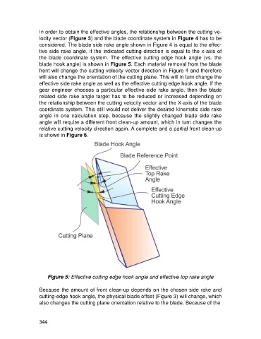
the blade coordinate system. The effective cutting edge hook angle (vs. the
blade hook angle) is shown in Figure 5. Each material removal from the blade
front will change the cutting velocity vector direction in Figure 4 and therefore
will also change the orientation of the cutting plane. This will in turn change the
effective side rake angle as well as the effective cutting edge hook angle. If the
gear engineer chooses a particular effective side rake angle, then the blade
related side rake angle target has to be reduced or increased depending on
the relationship between the cutting velocity vector and the X-axis of the blade
coordinate system. This still would not deliver the desired kinematic side rake
angle in one calculation step, because the slightly changed blade side rake
angle will require a different front clean-up amount, which in turn changes the
relative cutting velocity direction again. A complete and a partial front clean-up
is shown in Figure 6.
Figure 5: Effective cutting edge hook angle and effective top rake angle
Because the amount of front clean-up depends on the chosen side rake and
cutting-edge hook angle, the physical blade offset (Figure 3) will change, which
also changes the cutting plane orientation relative to the blade. Because of the
344