
Page 362 - Gear Technology Solutions
P. 362
shows the correct effective cutting edge hook angle as well as the correct front
clean-up.
The result of the effective side rake after finishing the first step of the iteration
will not deliver the desired effective side rake angle because the two inner
loops in Figure 7 changed the cutting direction relative to the blade coordinate
system enough, that several corrective repetitions of this loop are required.
Corrective input is the deviation (with negative sign) between actual and nomi-
nal effective side rake angle. Although this procedure makes this loop an itera-
tion, the loop ends either if the deviation limit is satisfied or after maximally 5
steps.
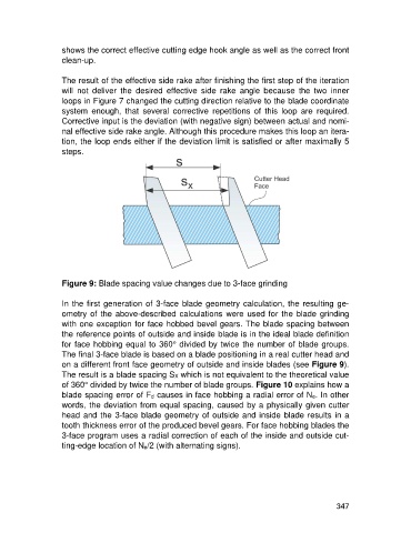
Figure 9: Blade spacing value changes due to 3-face grinding
In the first generation of 3-face blade geometry calculation, the resulting ge-
ometry of the above-described calculations were used for the blade grinding
with one exception for face hobbed bevel gears. The blade spacing between
the reference points of outside and inside blade is in the ideal blade definition
for face hobbing equal to 360° divided by twice the number of blade groups.
The final 3-face blade is based on a blade positioning in a real cutter head and
on a different front face geometry of outside and inside blades (see Figure 9).
The result is a blade spacing SX which is not equivalent to the theoretical value
of 360° divided by twice the number of blade groups. Figure 10 explains how a
blade spacing error of Fd causes in face hobbing a radial error of Ne. In other
words, the deviation from equal spacing, caused by a physically given cutter
head and the 3-face blade geometry of outside and inside blade results in a
tooth thickness error of the produced bevel gears. For face hobbing blades the
3-face program uses a radial correction of each of the inside and outside cut-
ting-edge location of Ne/2 (with alternating signs).
347