
Page 357 - Gear Technology Solutions
P. 357
3-face grinding of blades which will be utilized in a cutter head with 4.42° of
slot tilt angle is very limited with the maximal achievable top rake angle, which
is around zero as shown in the left graphic in Figure 1. If the same blade was
used in a cutter head with a 12° slot tilt angle as shown to the right in Figure 1,
then the achieved top rake angle would be 7.58°. This freedom allows in all
cases of different gear geometries and cutting kinematics to maintain a slightly
positive top rake angle.
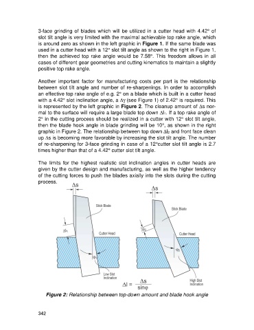
Another important factor for manufacturing costs per part is the relationship
between slot tilt angle and number of re-sharpenings. In order to accomplish
an effective top rake angle of e.g. 2° on a blade which is built in a cutter head
with a 4.42° slot inclination angle, a Dg(see Figure 1) of 2.42° is required. This
is represented by the left graphic in Figure 2. The cleanup amount of Ds nor-
mal to the surface will require a large blade top down Dl1. If a top rake angle of
2° in the cutting process should be realized in a cutter with 12° slot tilt angle,
then the blade hook angle in blade grinding will be 10°, as shown in the right
graphic in Figure 2. The relationship between top down D 2 and front face clean
l
up Ds is becoming more favorable by increasing the slot tilt angle. The number
of re-sharpening for 3-face grinding in case of a 12°cutter slot tilt angle is 2.7
times higher than that of a 4.42° cutter slot tilt angle.
The limits for the highest realistic slot inclination angles in cutter heads are
given by the cutter design and manufacturing, as well as the higher tendency
of the cutting forces to push the blades axially into the slots during the cutting
process.
Figure 2: Relationship between top-down amount and blade hook angle
342