
Page 352 - Gear Technology Solutions
P. 352
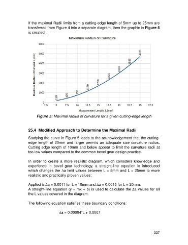
If the maximal Radii limits from a cutting-edge length of 5mm up to 25mm are
                   transferred from Figure 4 into a separate diagram, then the graphic in Figure 5
                   is created.


                         Figure 5: Maximal radius of curvature for a given cutting-edge length


                   25.4  Modified Approach to Determine the Maximal Radii

                   Studying the curve in Figure 5 leads to the acknowledgement that the cutting-
                   edge length of 20mm and  larger permits an  adequate  size  curvature  radius.
                   Cutting edge length of 10mm and below appear to limit the curvature radii at
                   too low values compared to the common bevel gear design practice.

                   In  order  to  create  a  more  realistic  diagram,  which  considers  knowledge  and
                   experience  in  bevel  gear  technology,  a  straight-line  equation  is  introduced
                   which changes the Da limit values between L = 5mm and L = 25mm to more
                   realistic and practically proven values:

                   Applied is Da = 0.0011 for L = 10mm and Da = 0.0015 for L = 20mm.
                   A straight-line equation (y = mx + b) is used to calculate the Da values for all
                   the L values covered in the diagram.

                   The following equation satisfies these boundary conditions:

                                       Da = 0.00004*L + 0.0007


                                                                                                     337