
Page 308 - Gear Technology Solutions
P. 308
Blad e
22 Blade Definitions Manual
22.1 Introduction to the Manual
This chapter is a manual with all the common geometric features of stick
blades for the cutting of bevel gears. The nomenclature for the different cutting
blade features has often not been clear. Gear engineers helped themselves
out of this conflict and created definitions that seemed to apply to the particular
geometrical feature. The introduction of a new and very innovative three-face
blade geometry deemed the requirement to establish or re-establish correct
and common terms and definitions. When the three-face blade grinding sum-
mary was developed, Gleason engineers from Research & Development as
well as from Application Engineering studied existing Gleason literature in or-
der to find the correct vocabulary as it has been defined in the past. Only in a
few cases, new definitions had to be adopted. Those were cases where the
function of a certain feature had not been known in the past, or it was neglect-
ed because its influence was not clear, and the older two-face geometry had
no freedom to change it. One example is the term “Kinematic Top Rake Veloci-
ty Angle”. The existence of this angle was neglected until the three-face soft-
ware was developed in 2009.
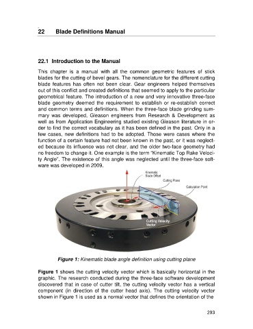
Figure 1: Kinematic blade angle definition using cutting plane
Figure 1 shows the cutting velocity vector which is basically horizontal in the
graphic. The research conducted during the three-face software development
discovered that in case of cutter tilt, the cutting velocity vector has a vertical
component (in direction of the cutter head axis). The cutting velocity vector
shown in Figure 1 is used as a normal vector that defines the orientation of the
293