
Page 306 - Gear Technology Solutions
P. 306
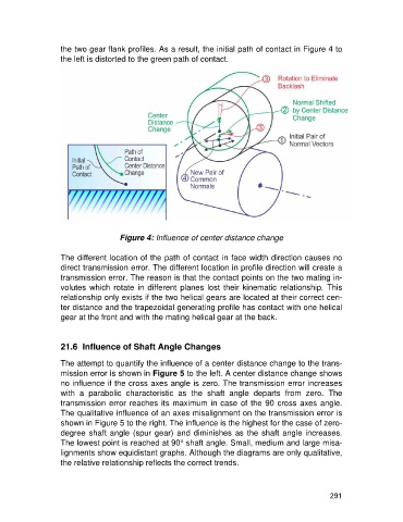
the two gear flank profiles. As a result, the initial path of contact in Figure 4 to
                   the left is distorted to the green path of contact.


                                     Figure 4: Influence of center distance change

                   The different location of the path of contact in face width direction causes no
                   direct transmission error. The different location in profile direction will create a
                   transmission error. The reason is that the contact points on the two mating in-
                   volutes  which  rotate  in  different  planes  lost  their  kinematic  relationship.  This
                   relationship only exists if the two helical gears are located at their correct cen-
                   ter distance and the trapezoidal generating profile has contact with one helical
                   gear at the front and with the mating helical gear at the back.


                   21.6  Influence of Shaft Angle Changes

                   The attempt to quantify the influence of a center distance change to the trans-
                   mission error is shown in Figure 5 to the left. A center distance change shows
                   no influence if the cross axes angle is zero. The transmission error increases
                   with  a  parabolic  characteristic  as  the  shaft  angle  departs  from  zero.  The
                   transmission error reaches its maximum in case of the 90 cross axes angle.
                   The qualitative influence of an axes misalignment on the transmission error is
                   shown in Figure 5 to the right. The influence is the highest for the case of zero-
                   degree shaft angle (spur gear) and diminishes as the shaft  angle increases.
                   The lowest point is reached at 90° shaft angle. Small, medium and large misa-
                   lignments show equidistant graphs. Although the diagrams are only qualitative,
                   the relative relationship reflects the correct trends.


                                                                                                     291