
Page 203 - Gear Technology Solutions
P. 203
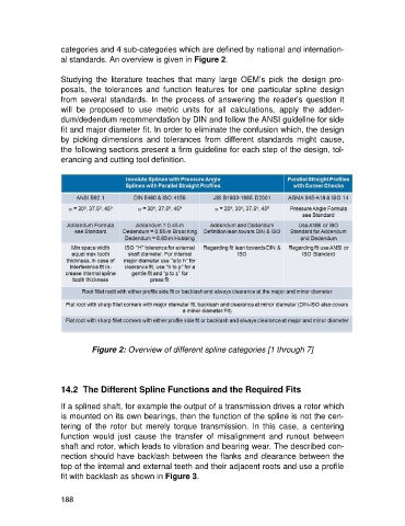
categories and 4 sub-categories which are defined by national and internation-
                   al standards. An overview is given in Figure 2.

                   Studying  the  literature  teaches  that  many  large  OEM’s  pick  the  design  pro-
                   posals,  the  tolerances  and  function  features  for  one  particular  spline  design
                   from several standards. In the process  of answering  the reader’s  question it
                   will  be  proposed  to  use  metric  units  for  all  calculations,  apply  the  adden-
                   dum/dedendum recommendation by DIN and follow the ANSI guideline for side
                   fit and major diameter fit. In order to eliminate the confusion which, the design
                   by  picking  dimensions  and  tolerances  from  different  standards  might  cause,
                   the following sections present a firm guideline for each step of the design, tol-
                   erancing and cutting tool definition.


                             Figure 2: Overview of different spline categories [1 through 7]


                   14.2  The Different Spline Functions and the Required Fits

                   If a splined shaft, for example the output of a transmission drives a rotor which
                   is mounted on its own bearings, then the function of the spline is not the cen-
                   tering  of  the  rotor  but  merely  torque  transmission.  In  this  case,  a  centering
                   function  would  just  cause  the  transfer  of  misalignment  and  runout  between
                   shaft and rotor, which leads to vibration and bearing wear. The described con-
                   nection should have backlash between the flanks and clearance between the
                   top of the internal and external teeth and their adjacent roots and use a profile
                   fit with backlash as shown in Figure 3.


                   188