
Page 181 - Gear Technology Solutions
P. 181
A graphic of the orientation between grinding wheel and Curvic coupling mem-
bers is shown in Figure 15. In this graphic the outside of the grinding wheel
profile forms two concave flanks of the member with hourglass shaped teeth
(left). In one revolution all teeth are finish ground. The opposite member is
ground with the inside profile of a different grinding wheel and forms two con-
vex flanks simultaneously which results in hourglass shaped teeth (right graph-
ic in Figure 15). The wheel point diameter between the left and right graphic is
adjusted such that either a full-face width contact or a located contact pattern
is achieved. Profile crowning is also possible by dressing a curved grinding
wheel profile.
It becomes clear that a single tooth and slot centering force requires a high
accuracy of the tooth surfaces. In many steam turbines more than 50 rotors
are bolted together to one unit. The radial centering has to provide low radial
runout, but also the axial runout has to be in the fractional micron range in or-
der to minimize the unbalancing of a long rotor unit. There is software available
which uses spacing measurement results from coordinate measuring ma-
chines to calculate an optimal timing between two rotors. If all rotors are as-
sembled with their optimal Curvic coupling timing, then the overall runout and
unbalance of a long rotor unit can be minimized to sustain highest rotational
speeds.
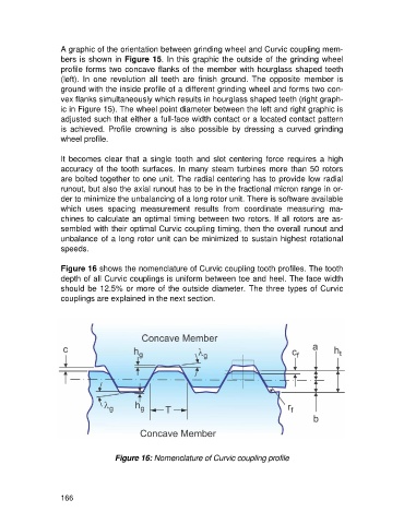
Figure 16 shows the nomenclature of Curvic coupling tooth profiles. The tooth
depth of all Curvic couplings is uniform between toe and heel. The face width
should be 12.5% or more of the outside diameter. The three types of Curvic
couplings are explained in the next section.
Figure 16: Nomenclature of Curvic coupling profile
166