
Page 179 - Gear Technology Solutions
P. 179
The process in Figure 12 is not a standard Coniflex coupling grinding process.
Based on the large part and the large face width, the UNIFLEX process was
applied [4]. In Uniflex, the grinding wheel moves along the face width and pro-
duces a straight root line, independent from the grinding wheel diameter.
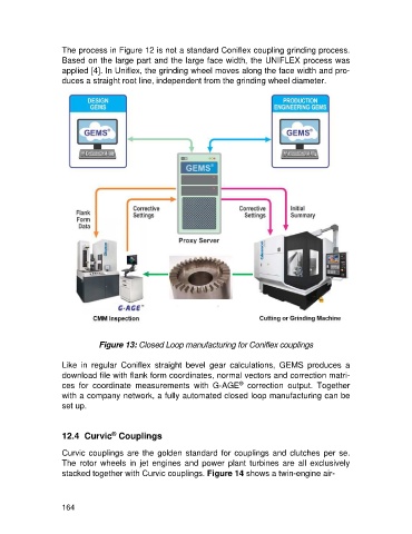
Figure 13: Closed Loop manufacturing for Coniflex couplings
Like in regular Coniflex straight bevel gear calculations, GEMS produces a
download file with flank form coordinates, normal vectors and correction matri-
®
ces for coordinate measurements with G-AGE correction output. Together
with a company network, a fully automated closed loop manufacturing can be
set up.
®
12.4 Curvic Couplings
Curvic couplings are the golden standard for couplings and clutches per se.
The rotor wheels in jet engines and power plant turbines are all exclusively
stacked together with Curvic couplings. Figure 14 shows a twin-engine air-
164