
Page 154 - Gear Technology Solutions
P. 154
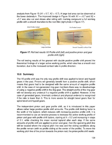
analysis from Figure 15 (X1 = 0.7, X2 = -0.7). A large lost area can be observed at
                   the lower dedendum. The improved design in Figure 16 with X1 = +0.7 and X2 =
                   +0.7 was also cut and shows after rolling with marking compound a full working
                   profile with a smooth transition to the root fillet (right photo in Figure 17).


                       Figure 17: Roll test results V0 Profile shift (left) and positive pinion and gear
                                                     profile shift (right)

                   The roll testing results of the gearset with double positive profile shift proved the
                   theoretical findings of a larger active working profile, which also has a smooth root
                   transition, due to the increased contact ratio in profile direction.


                   10.6  Summary

                   The V0 profile shift was the only way profile shift was applied to bevel and hypoid
                   gears in the past. Pinions will generally benefit from a positive profile shift, which
                   means that gears had to be designed with the same amount of negative profile
                   shift. In the case of non-generated ring gear members there was no disadvantage
                   of using a negative profile shift in the ring gear. The straight profile of the ring gear
                   will not develop any undercut if a negative profile shift is applied. However, in the
                   case of generated gears, kinematic undercut and physical undercut is recognized
                   if the ratio is lower than 3. This is more severe for straight bevel gears than for
                   spiral bevel and hypoid gears.

                   The  independent  pinion  and  gear  profile  shift,  as  it  is  introduced  in  this  paper
                   allows rather large positive profile shift amounts. The profile shift limiting factor is
                   the width of the topland, which reduces with increasing positive profile shift. It is
                   recommended to use an iterative process to increase the active working profile of
                   pinion and gear with profile shift factors, starting at X = 0.2 and increasing in steps
                   of  0.1,  while  checking  the  mean  normal  topland  after  each  step.  If  the  same
                   amounts of profile shift are applied to pinion and gear, then the operating pitch line
                   will be located where the original pitch line was and the sliding conditions along
                   the profile remain (with no profile sliding at the center of the profile). To move the
                   working pitch line of the pinion towards the pinion root, the pinion profile shift needs


                                                                                                     139