
Page 66 - Gear Technology Solutions
P. 66
tions. As mentioned above, already small deflections at moderate loads lead to
load concentrations on the edges of conjugate flank pairs and can cause mate-
rial damage and considerable noise emission. As such, the conjugate gear pair
is not suitable for any task in power transmissions.
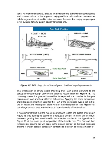
Figure 15: TCA of hypoid set from Figure 11 without any displacements
The introduction of 80mm length crowning and 15mm profile crowning to the
conjugate hypoid design delivers the analysis results shown in Figure 15. The
crowning makes the gearset insensitive to expected inaccuracies in the gear
housing and load and heat affected deflections. Applying the same amounts of
shaft displacements then used for the TCA of the conjugate hypoid set in Fig-
ure 14 moves the mean point slightly out of the initial position (see Figure 16),
but a large contact area within the tooth boundaries is still maintained.
It was demonstrated that the hypoid gearset with length and profile crowning in
Figure 15 was developed based on a conjugate design. The first and third fun-
damental gearing law, mentioned in this chapter, applies to the hypoid set in
Figure 15 at the mean point roll position, if the load is zero. The first and third
fundamental gearing law will apply in the area of contact as the load increases
and the Hertzian contact spreads in contact line direction as well as in path of
51