
Page 300 - Gear Technology Solutions
P. 300
20.6 Application of the Tolerances
The tolerance values in the tables for the specific gear types have been de-
fined independently from each other to change the backlash not more than
50% of the backlash range defined in Table 1. If for example the entire nega-
tive tolerance for the root angle (ALPHA) and for the gear cone (G) is used
simultaneously, then the backlash would be below the recommended minimal
value, however there will still be acceptable backlash available.
If a manufacturer can accept a backlash range which is twice the range shown
in Table 1, then all the shaft positioning tolerances from the tables can be di-
rectly transferred in the housing print. If a manufacturer likes to control the
backlash within the range of Table 1, then the values of the combined toler-
ances for the housing print have to be calculated by applying the axis specific
percentages from Table 8.
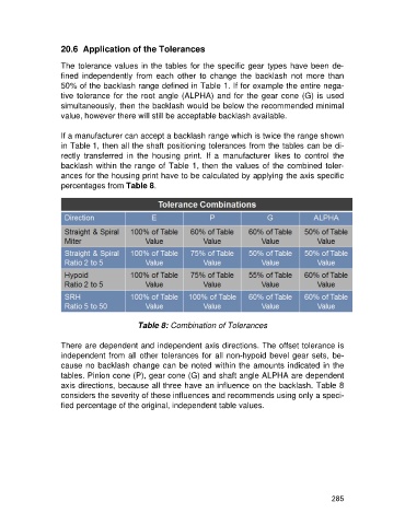
Table 8: Combination of Tolerances
There are dependent and independent axis directions. The offset tolerance is
independent from all other tolerances for all non-hypoid bevel gear sets, be-
cause no backlash change can be noted within the amounts indicated in the
tables. Pinion cone (P), gear cone (G) and shaft angle ALPHA are dependent
axis directions, because all three have an influence on the backlash. Table 8
considers the severity of these influences and recommends using only a speci-
fied percentage of the original, independent table values.
285