
Page 296 - Gear Technology Solutions
P. 296
A simplified graphic demonstrates in Figure 6 the influence to the backlash if
the gear cone distance G is changed. If the theoretical backlash is defined
precisely in the middle of the tolerance given in Table 1, then any of the shaft
positioning tolerances, or the worst-case combination of those tolerances shall
not change the backlash to a value outside of the given tolerances. The follow-
ing shaft positioning tolerance tables are based on the maximally permissible
contact movement and the maximally allowed backlash change. Both criteria
are evaluated for each shaft deviation tolerance. The tolerance value was de-
fined at the point when the permissible limit of one criterion was reached.
If the backlash is set in the transmission housing during assembly e.g. by a
gear cone adjustment, then it appears always possible to obtain correct back-
lash independent from the shaft positioning tolerances. However, such a back-
lash adjustment would in case of shaft deviations, which exceed the recom-
mended values in the following tables, result in unacceptably large tooth con-
tact position errors and distortions. Therefore, the following tables are also val-
id in case of individual backlash setting in the transmission assembly.
20.5 Shaft Deviation Tolerances for Bevel and Hypoid Gears
The following tables for the different bevel gear types show, sorted by module,
the E, P, G and ALHPHA tolerance values. The last row lists the expected but
permissible contact movement in case of maximal shaft positioning errors,
provided these are within the mentioned tolerance limits.
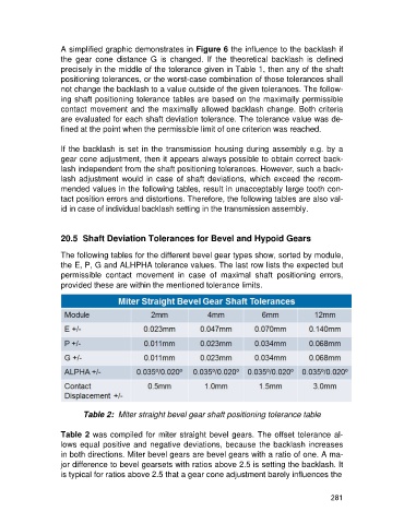
Table 2: Miter straight bevel gear shaft positioning tolerance table
Table 2 was compiled for miter straight bevel gears. The offset tolerance al-
lows equal positive and negative deviations, because the backlash increases
in both directions. Miter bevel gears are bevel gears with a ratio of one. A ma-
jor difference to bevel gearsets with ratios above 2.5 is setting the backlash. It
is typical for ratios above 2.5 that a gear cone adjustment barely influences the
281