
Page 293 - Gear Technology Solutions
P. 293
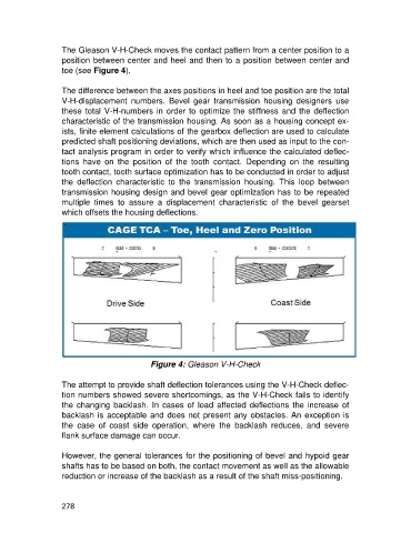
The Gleason V-H-Check moves the contact pattern from a center position to a
                   position between center and heel and then to a position between center and
                   toe (see Figure 4).

                   The difference between the axes positions in heel and toe position are the total
                   V-H-displacement  numbers.  Bevel  gear  transmission  housing  designers  use
                   these total V-H-numbers in order to optimize the stiffness and the deflection
                   characteristic of the transmission housing. As soon as a housing concept ex-
                   ists, finite element calculations of the gearbox deflection are used to calculate
                   predicted shaft positioning deviations, which are then used as input to the con-
                   tact analysis program in order to verify which influence the calculated deflec-
                   tions  have  on  the  position  of  the  tooth  contact.  Depending  on  the  resulting
                   tooth contact, tooth surface optimization has to be conducted in order to adjust
                   the  deflection  characteristic  to  the  transmission  housing.  This  loop  between
                   transmission housing design and bevel gear optimization has to be repeated
                   multiple  times  to  assure  a  displacement  characteristic  of  the  bevel  gearset
                   which offsets the housing deflections.
                    .


                                              Figure 4: Gleason V-H-Check

                   The attempt to provide shaft deflection tolerances using the V-H-Check deflec-
                   tion numbers showed severe shortcomings, as the V-H-Check fails to identify
                   the  changing  backlash.  In  cases  of  load  affected  deflections  the  increase  of
                   backlash is acceptable and does not present any obstacles. An exception is
                   the  case  of  coast  side  operation,  where  the  backlash  reduces,  and  severe
                   flank surface damage can occur.

                   However, the general tolerances for the positioning of bevel and hypoid gear
                   shafts has to be based on both, the contact movement as well as the allowable
                   reduction or increase of the backlash as a result of the shaft miss-positioning.


                   278