
Page 241 - Gear Technology Solutions
P. 241
The additional possibilities of distorting the sinusoidal correction function with a
frequency and amplitude change between the toe and heel section and the intro-
duction of a dwell section have improved the practical results in production even
more.
Fast Fourier Transformation (FFT) of the single flank test results of a baseline
hypoid gearset are shown in the top graphic in Figure 16. When the Micro-
Form was switched on in the grinding machine, the levels of all mesh harmonic
th
frequencies (except the 11 harmonic) had been reduced.
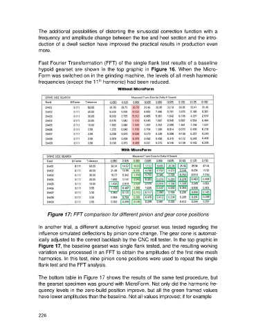
Figure 17: FFT comparison for different pinion and gear cone positions
In another trial, a different automotive hypoid gearset was tested regarding the
influence simulated deflections by pinion cone change. The gear cone is automat-
ically adjusted to the correct backlash by the CNC roll tester. In the top graphic in
Figure 17, the baseline gearset was single flank tested, and the resulting working
variation was processed in an FFT to obtain the amplitudes of the first nine mesh
harmonics. In this test, nine pinion cone positions were used to repeat the single
flank test and the FFT analysis.
The bottom table in Figure 17 shows the results of the same test procedure, but
the gearset specimen was ground with MicroForm. Not only did the harmonic fre-
quency levels in the zero-build position improve, but all the green framed values
have lower amplitudes than the baseline. Not all values improved; if for example
226