
Page 206 - Gear Technology Solutions
P. 206
The effective pressure angle can be calculated from the triangle in Figure 6,
using the reference diameter as hypotenuse and the tooth thickness as the
opposite side. The straight sided spline according to AGMA has checks at the
root fillets (see Figure 6). There is no particular preference in the standards
regarding diameter fit or flank fit. Also, for the parallel sided spline it is common
to either use a major diameter fit with clearance on the flanks or a major diam-
eter fit with a gentle fit or press fit on the flanks. Flank fit without major diame-
ter fit is uncommon because a radial misalignment due to a press fit is more
likely than in case of splines with non-parallel flanks.
14.3 Defining the Spline Dimensions
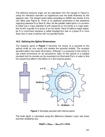
The example spline in Figure 7 transmits the torque of a sprocket to the
splined shaft (or vice versa) and centers the sprocket radially. The example
sprocket spline has metric dimensions. Although it is proposed in this article to
use metric dimensions for all calculations, later, for the search of a suitable
standard hob the module can be converted into Diametral Pitch, in order to find
the closest hob either in the Metric of in the Imperial system.
Figure 7: Example sprocket with internal spline
The tooth depth is calculated using the difference between major and minor
diameter divided by two:
Depth = (dMajor – dMinor)/2 = 2mm
191