
Page 166 - Gear Technology Solutions
P. 166
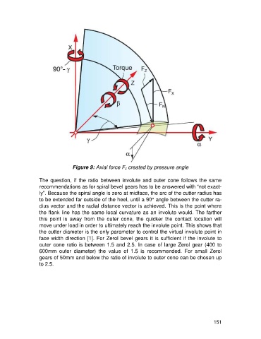
Figure 9: Axial force Fz created by pressure angle

                   The question,  if the  ratio  between involute  and outer cone follows the same
                   recommendations as for spiral bevel gears has to be answered with “not exact-
                   ly”. Because the spiral angle is zero at midface, the arc of the cutter radius has
                   to be extended far outside of the heel, until a 90° angle between the cutter ra-
                   dius vector and the radial distance vector is achieved. This is the point where
                   the flank line has the same local curvature as an involute would. The farther
                   this  point  is  away  from  the  outer  cone,  the  quicker  the  contact  location  will
                   move under load in order to ultimately reach the involute point. This shows that
                   the cutter diameter is the only parameter to control the virtual involute point in
                   face width direction [1]. For Zerol bevel gears it is sufficient if the involute to
                   outer cone ratio is between 1.5 and 2.5. In case of large Zerol gear (400 to
                   600mm  outer  diameter)  the  value  of  1.5  is  recommended.  For  small  Zerol
                   gears of 50mm and below the ratio of involute to outer cone can be chosen up
                   to 2.5.


                                                                                                     151