
Page 163 - Gear Technology Solutions
P. 163
degree spiral angle and any other larger spiral angle would be possible, how-
ever, the geometry of a true Zerol and a true spiral bevel gear is slightly differ-
ent, which is why two different software packages had been developed to pro-
vide the optimal solution for both gear types.
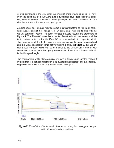
A spiral bevel gear design with the same input parameters as the Zerol calcu-
lation above, except the change to a 15° spiral angle was made also with the
GEMS software system. The tooth contact analysis results are presented in
Figure 7. The Ease-Off looks like expected from the input parameters and the
tooth contact pattern below the Ease-Off are centered with the expected width.
The boundaries of the tooth have a moderate slot depth taper between heel
and toe with a reasonably large active working profile. In Figure 8, the Dimen-
sion Sheet is shown which can be compared to the Dimension Sheets in Fig-
ures 6 and 4 to see that the input parameters of all three calculations only dif-
fer by the spiral angle.
The comparison of the three calculations with different spiral angles makes it
evident that the transition between a true Zerol bevel gearset and a spiral bev-
el gearset are fluent without any visible abrupt changes.
Figure 7: Ease-Off and tooth depth dimensions of a spiral bevel gear design
with 15° spiral angle at midface
148