
Page 170 - Gear Technology Solutions
P. 170
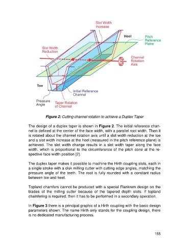
Figure 2: Cutting channel rotation to achieve a Duplex Taper

                   The design of a duplex taper is shown in Figure 2. The initial reference chan-
                   nel is defined at the center of the face width, with a parallel root width. Then it
                   is rotated about the channel rotation axis until a slot width reduction at the toe
                   and a slot width increase at the heel (measured in the pitch reference plane) is
                   achieved.  The  slot  width  change  results  in  a  slot  width  taper  along  the  face
                   width, which is proportional to the circumference of the pitch cone at the re-
                   spective face width position [2].

                   The duplex taper makes it possible to machine the Hirth coupling slots, each in
                   a single stroke with a disk milling cutter with cutting edge angles, matching the
                   pressure angle of the teeth. The root is fully rounded with a constant radius
                   between toe and heel.

                   Topland chamfers cannot be produced with a special Flankrem design on the
                   blades  of  the  milling  cutter  because  of  the  tapered  depth  slots.  If  topland
                   chamfering is required, then it has to be performed in a secondary operation.

                   In Figure 3 there is a principal graphic of a Hirth coupling with the basic design
                   parameters shown. The name Hirth only stands for the coupling design, there
                   is no dedicated manufacturing process.


                                                                                                     155