
Page 169 - Gear Technology Solutions
P. 169
possible, because of the fact that both coupling and clutch members are facing
each other without any possibility of a defined relative motion between them.
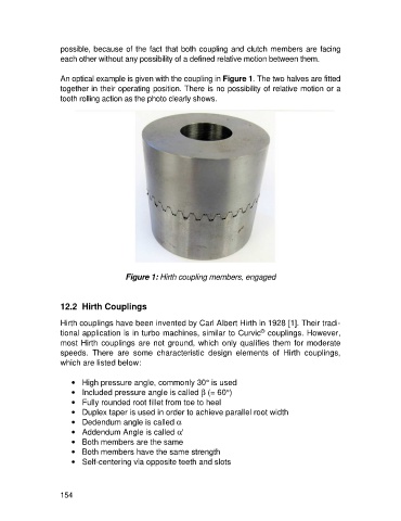
An optical example is given with the coupling in Figure 1. The two halves are fitted
together in their operating position. There is no possibility of relative motion or a
tooth rolling action as the photo clearly shows.
Figure 1: Hirth coupling members, engaged
12.2 Hirth Couplings
Hirth couplings have been invented by Carl Albert Hirth in 1928 [1]. Their tradi-
®
tional application is in turbo machines, similar to Curvic couplings. However,
most Hirth couplings are not ground, which only qualifies them for moderate
speeds. There are some characteristic design elements of Hirth couplings,
which are listed below:
· High pressure angle, commonly 30° is used
· Included pressure angle is called b (= 60°)
· Fully rounded root fillet from toe to heel
· Duplex taper is used in order to achieve parallel root width
· Dedendum angle is called a
· Addendum Angle is called a'
· Both members are the same
· Both members have the same strength
· Self-centering via opposite teeth and slots
154