
Page 89 - Gear Technology Solutions
P. 89
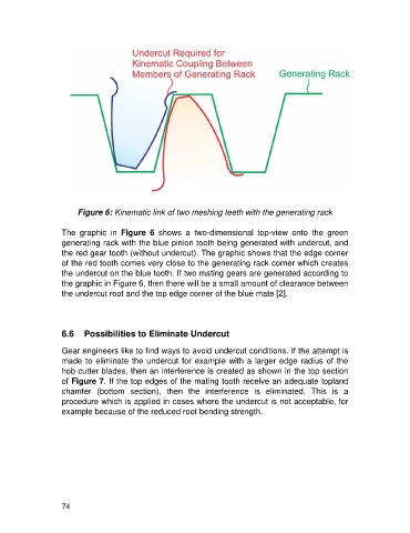
Figure 6: Kinematic link of two meshing teeth with the generating rack

                   The  graphic  in  Figure  6  shows  a  two-dimensional  top-view  onto  the  green
                   generating rack with the blue pinion tooth being generated with undercut, and
                   the red gear tooth (without undercut). The graphic shows that the edge corner
                   of the red tooth comes very close to the generating rack corner which creates
                   the undercut on the blue tooth. If two mating gears are generated according to
                   the graphic in Figure 6, then there will be a small amount of clearance between
                   the undercut root and the top edge corner of the blue mate [2].


                   6.6   Possibilities to Eliminate Undercut

                   Gear engineers like to find ways to avoid undercut conditions. If the attempt is
                   made to eliminate the undercut for example with a larger edge radius of the
                   hob cutter blades, then an interference is created as shown in the top section
                   of Figure 7. If the top edges of the mating tooth receive an adequate topland
                   chamfer  (bottom  section),  then  the  interference  is  eliminated.  This  is  a
                   procedure which is applied in cases where the undercut is not acceptable, for
                   example because of the reduced root bending strength.


                   74